IPv6, Secure and Private AI are both upon us, and Cohesive Networks is delivering into those areas with the same practical approach we have used for Public and Private Cloud all these years.
Stand Apart – but be Cohesive
read more

VNS3 6.0 Beta3 will be available in cloud marketplaces or upon request this week (contactme@www.cohesive.net). In our last post we showed how easy it is to connect your native WireGuard® clients to VNS3 6.0. In this post we show you how to use the Cohesive VPN Client to achieve the same goals like connecting to data centers or cloud VPCs/VNETs, and managing your own WireGuard® network connecting multiple people and devices. In addition, we will show an overview of using our enterprise capabilities like dynamic route updates, easy tunneling of all traffic with local subnet exceptions, and OIDC integration so you can authenticate your vpn users with Google Authentication, Okta, Auth0 and more.
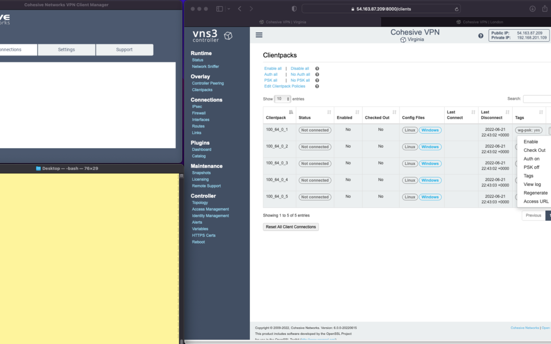
The screen shots throughout show three windows; upper left the Cohesive VPN client, bottom left a command line from the same Mac, and to the right the cloud-based VNS3 server.
VNS3 Network Platform has the concept of “clientpacks” – basically the credentials needed to connect a machine or a person to the network via a VPN client. Historically “clientpacks” have been “openvpn” by default. Starting in 6.0 clientpacks are WireGuard by default. In a future release we will support a dual stack with both “ovpn” and “wg” connections simultaneously, and a goal of IPsec clients as well.
In the picture above and those below we show the “Clientpacks” page. From this you can perform key administrative functions like disabling addresses, re-generating credentials, updating pre-shared keys, and getting access URLs for secure and easy distribution of VPN credentials.


Above shows the results of choosing “Access URL” and displaying its result. This is a secure, one-time, timed URL allowing users to copy/paste the clientpack, download it for import, or use via a QR code on mobile devices.
It has all the necessary information to make a connection using the Cohesive VPN Client – with or without PSKs.
The commented lines are used by CNVPN CLI and GUI for additional enterprise support; failover, dynamic route updates, and OIDC authentication.
Copy/paste the clientpack into the Cohesive client via the “Paste” option, and choose Save.


Next choose “Connect” from the Cohesive Client’s “Actions” menu – and the VPN connection is created. The VNS3 Clientpacks page then shows the status as “connected”.
Below shows access to the VPN network by successfully pinging the VNS3 controller’s VPN address. (By default, this connection can access other addresses on the VPN. If that’s not desired it is easily changed via the Firewall page.)


You can use the Action menu on the VNS3 Clientpacks page to perform administrative operations. For example, if you select “Disable” on the connection, the client is dropped from the VPN.
Similar operations can be performed to re-new or re-secure a connection by adding a PSK or re-generating keys (both of which require the clientpack to be redistributed to the user or device). As expected, when you enable a PSK for the connection, the user is unable to access the network. With the credential re-deployed with the appropriate clientpack containing the PSK, they are back on the net!
To see some of those operations in action, take a look at our previous post. Cohesive’s target is to provide organizations the ability to deploy their own enterprise VPN infrastructure. This could be managed by Cohesive via our SecurePass offering, or self-managed. Regardless, our initial focus for 6.0 is managed, enterprise WireGuard.
One of our key enterprise features is dynamic route updates. For “people vpns” you can usually just tunnel all traffic through the VPN – making the VPN adapter the default gateway. However, for IoT and machine2machine vpns, dynamic routing is a critical capability. You allow the device to have its own local gateway but when routes arrive dynamically, the traffic begins to follow that path. If the route is removed from the network, the default gateway is used.
In the example below the configuration is changed to have “RoutePolling = True”, and on the VNS3 controller a route to 55.55.55.55 has been advertised through the VPN. In the terminal window route display there is not yet a specific route to that public IP.
Once re-connected, the route to 55.55.55.55 through the VPN is visible on the client as a result of the dynamic route updating.
If that route is disabled or removed from the VPN network, then it is removed from the client.


Tunneling all traffic through the VPN to the Internet is a snap with the Cohesive VPN Client.
Set the client parameter “TunnelAllTraffic” to “True” AND make sure you have enabled firewall directives on the VNS3 Server to send all VPN traffic out to the Internet.
VNS3 Free edition comes with a default set of rules in a group called “VPN2Internet. Go to the Groups view on the Firewall page and enable these rules.
This will direct all traffic from your VPN client to the Internet, getting its address translated to the Public IP of the VNS3 controller.
What if you still want to be able to access local network resources like a printer or file server? In that case, use the “LocalRoutes” option to enter a comma delimited list of the network CIDRs you want to exempt from the VPN so they can be reached locally.
Now that all traffic is being tunneled, from the command line the public IP 8.8.8.8 can be successfully pinged. To “prove” this traffic is going into the VPN we show it via our Network Sniffer.


So far the examples have just used WireGuard protocol with unique keys and pre-shared key (PSK) for the connections. What about more specific user authentication? For WireGuard in VNS3 6.0 we use OIDC (Open ID Connect), and will add LDAP support in future. (Our dual stack offering in future will allow simultaneous use of OpenVPN and WireGuard clients, with your choice of LDAP/AD or OIDC).
With OIDC support you create a VPN users and/or admins application in your OIDC provider and then configure VNS3 integration.

Once the OIDC configuration has been saved you can login. In this case we are using our Google Apps login. When “Connect” is chosen, a login screen pops up in the default browser.

Upon entering the correct password the login panel indicates success and the VPN client connects!

Next up we will show using the Cohesive CNVPN CLI on a Linux machine. For cloud overlay networks and over-the-top cloud networking, the CLI is a powerful way to bring your enterprise feature set to your cloud and multi-cloud deployments.
(“WireGuard” and the “WireGuard” logo are registered trademarks of Jason A. Donenfeld.)

VNS3 6.0 Beta2 is now available.
You can find the Free edition in both the Amazon and Azure marketplaces (GCP coming soon).
It is an easy way to get a server up and running that can connect you to data centers, cloud VPCs/VNETs, has a super firewall, straightforward support of even difficult things like “source based routing”, and most of all a quick way to run and manage your own WireGuard® network connecting multiple people, devices, or both.
This post will show you how to use the standard Mac Appstore WireGuard client built and delivered by the WireGuard team with Cohesive Networks VNS3 6.0 network controllers. (Of course similar capability is available using the same app from the Windows/iPhone/Android “app stores” as well.)
In future posts we will show the Cohesive CLI (cnvpn) at work, and the Cohesive WG GUI working with VNS3 6.0. And then we will follow up by showing how the different connection options work with a distributed VPN cluster where you can spread a VNS3 controller mesh across regions and clouds with ease, yet have a unified VPN system for management of credentials, pre-shared keys, OIDC sessions and more.
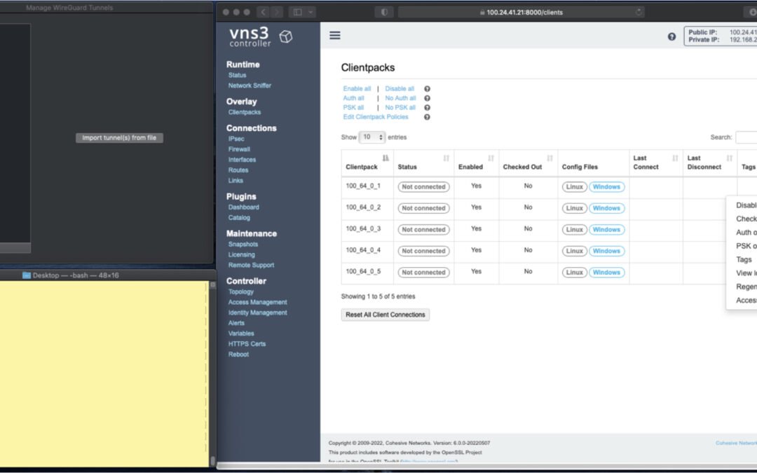
In the screen shots throughout we have three windows; upper left the Mac OS WG client, bottom left a command line from the same Mac, and to the right the cloud-based VNS3 server supporting a wide range of cloud networking use-cases, and here specifically WireGuard VPN connections.
VNS3 Network Platform has the concept of “clientpacks” – basically the credentials needed to connect a machine or a person via a VPN client to the network. Historically they have been “openvpn” by default – and starting in 6.0 they are WireGuard by default. In a future release we will support a dual stack with both “ovpn” and “wg” connections simultaneously, and a goal of IPsec clients as well.
In the picture above and those below we see the “Clientpacks” page. From here you can perform key administrative functions like disabling addresses, re-generating credentials, updating pre-shared keys, and getting access URLs for secure and easy distribution of VPN credentials.

Above shows the results of choosing “Access URL” and displaying its result. This is a secure, one-time, timed URL which allows users to copy/paste the clientpack, download it for import, or for mobile clients use a QR code for import.
It has all the necessary information to make a connection using the standard WG Client – with or without PSKs.
There is also a series of commented lines which are used by CNVPN CLI and GUI for additional enterprise support (failover, dynamic route updates, OIDC authentication) to be discussed in future. For now we just want to focus on how easy it is to connect native WG clients.
Copy/paste the clientpack into the Mac OS client, and click SAVE/ACTIVATE.

Voilà – you are connected to the VPN. The VNS3 Clientpacks page shows the status as “connected”.
The WG Client now shows its statistics about the connection, and below we are pinging the VNS3 controller’s VPN address to show access to the VPN network.
(By default, this connection can access other addresses on the VPN. If that’s not desired it is easily changed via the Firewall page.)

If needed you can use the Action menu to perform administrative operations. For example, if you select “Disable” on the connection, the client is dropped from the VPN. Below, we see the client set to disabled state by the Admin, and we see the “pings” begin to fail.
Then we “Enable” – and the client is back on the network and packets begin to flow.


And of course similar operations can be performed to re-new or re-secure a connection by adding a PSK or re-generating keys – both of which require the clientpack to be redistributed to the user or device. But as expected, when you enable a PSK for the connection, the user is unable to access the network. With the credential re-deployed with the appropriate clientpack containing the PSK, they are back on the net!


Accessing the other devices on the VPN network is one use, what about getting to the Internet?
This requires a couple configuration elements on the client side which requires a little bit of operating system knowledge on the client side and a of couple firewall rules on the VNS3 Controller. We won’t go into those specifics here.
But, if you look at the Cohesive-specific directives used by the CNVPN CLI and GUI – one of them is “TunnelAllTraffic” – and when this is set to “true” – all the client side magic is done for you! But that is for another day.
(“WireGuard” and the “WireGuard” logo are registered trademarks of Jason A. Donenfeld.)
In part I of our NATe post we discussed economic advantages to replacing your AWS NAT Gateways with Cohesive Networks VNS3 NATe devices. We also walked through how to deploy them. In this follow up post I want to dig in a little into the some of the incredibly useful capabilities that VNS3 NATe provides.
In part I we discussed how to replace your current NAT Gateway. One of the steps in that process was to repoint any VPC route table rules from the NAT gateway to the Elastic Network Interface (ENI) of the Elastic IP (EIP) that we moved to the VNS3 NATe ec2 instance. This was done for consistency so that if you had any rules in place that referenced that IP, you would remain intact. Unfortunately, due to the mechanics of AWS NAT Gateway, you can not reassign its EIP while it is running. So we had to delete it in order to free up the EIP. This part of the operation introduced 15 to 30 seconds of down time. With VNS3 NATe devices you can easily reassign an EIP without the need to delete an instance. Our upgrade path is to launch a new instance and move the EIP to it. Since we set our VPC route table rules to point to the ENI of the EIP, our routes will follow.
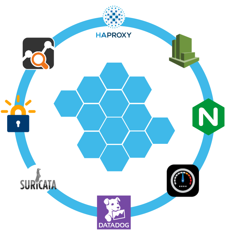
Another powerful feature of VNS3 NATe is the container plugin system. All VNS3 devices have a plugin system based around the docker subsystem. This allows our users to inject any open source, commercial or proprietary software into the network. Coupled with the VNS3 comprehensive firewall section, this becomes a versatile and powerful feature. In the case of a NAT device, there are some serious security concerns that can be addressed by leveraging this plugin system.

Suricata, the Network Intrusion Detection and Prevention System (IDS/IPS) developed by the Open Information Security Foundation (OISF) for the United States Department of Homeland Security (USDHS), is a powerful addition to a VNS3 NATe device. Modern day hacking is all about exfiltration of data. That data has to exit your network and the device that is in path is your NAT device. Additionally malware will often attempt to download additional software kits from the internet, this traffic also traverses through your NATe device. In both of the these scenarios Suricata has powerful features to analyze your traffic and identify suspicious activityand files. You can find directions for setting up Suricata on VNS3 here:
https://docs.cohesive.net/docs/network-edge-plugins/nids/
Additionally, Cohesive Networks has developed a Brightcloud Category Based Web Filtering Plugin. Brightcloud have created a distinct list of categories that all domain names have been divided into. The plugin takes advantage of this categorization in three ways:
These are just a few examples of software plugins that can run on VNS3 NATe. Others that will work are Snort, Bro (Zeek), Security Onion. Our Sales and Support teams are always happy to assist you in determining the right approach and assisting you with your implementation.

“Network address translation (NAT) is a method of mapping an IP address space into another by modifying network address information in the IP header of packets while they are in transit across a traffic routing device. The technique was originally used to avoid the need to assign a new address to every host when a network was moved, or when the upstream Internet service provider was replaced, but could not route the networks address space. It has become a popular and essential tool in conserving global address space in the face of IPv4 address exhaustion. One Internet-routable IP address of a NAT gateway can be used for an entire private network.”
Cohesive Networks introduced the NATe offering into our VNS3 lineup of network devices back in March. It lowers operational costs while adding functionality and increasing visibility. Easily deployable and managed, it should be a no brainer once you consider its functional gains and lower spend rate. Some of our large customers have already started the migration and are seeing savings in the tens, hundreds and thousands of thousands of dollars.
The AWS NAT Gateways provide bare bones functionality at a premium cost. They simply provide a drop in NAT function on a per availability zone basis within your VPC, nothing more.No visibility, no egress controls, and lots of hidden costs. You get charged between $0.045 and $0.093 an hour depending on the region. You get charged the same per gigabyte of data that they ‘process’, meaning data coming in and going out. That’s it, and it can really add up. A VPC with two availability zones will cost you $788.40 a year before data tax in the least expensive regions, going up to double that in the most expensive regions. Now consider that across tens, hundreds or thousands of VPCs. That’s some real money.
With Cohesive Networks VNS3 NATe you can run the same two availability zones on two t3a.nano instances with 1 year reserved instances as low as $136.66 per a year, with no data tax as ec2 instances do not incur inbound data fees. It is about a sixth to a tenth of the price depending on the region you are running in.
As a Solutions Architect at Cohesive Networks I’ve worked with enterprise customers around the world and understand the difficulty and challenges to change existing architecture and cloud design. Using cloud vender prescribed architecture is not always easy to replace as there are up and down stream dependancies. The really nice thing about swapping your NAT Gateways with VNS3 NATe devices is that it is really a drop in replacement for a service that is so well defined. It can be programatically accomplished to provide near zero downtime replacement. Then you can start to build upon all the new things that VNS3 NATe gives you.
The process of replacement is very straight forward:
The only downtime will be the 30 or so seconds that it takes to delete the NAT Gateway.
One safeguard we always recommend to our customers to set up a Cloud Watch Recovery Alarm on all VNS3 instances. This will protect your AWS instances from any underlining hardware and hypervisor failures. Which will give you effectively the same uptime assurancesas services like NAT Gateway. If the instance “goes away” the alarm will trigger an automatic recovery, including restoring the elastic ip, so that VPC route table rules remain intact as well as state as restoration occurs from run time cache.
Now you can log into your VNS3 NATe device by going to:
https://<elastic ip>:8000

usename: vnscubed

password: <ec2 instance-id>
Head over to the Network Sniffer page from the link on the left had side of the page and set up a trace for your private subnet range to get visibility into your NATe traffic.


Introduction to IPsec and VNS3
This is part 2 of our IPsec with VNS3 tutorial. Check out part one here.
In the previous tutorial we not only setup an IPsec connection but also created a Secure Edge using VNS3 and federated two major clouds. From here you could join your on-premise networks into your federated cloud environments using IPsec and TLS/SSL VPNs.
As promised last time, we’ll build on this environment and setup a Static Route-based IPsec connection.
What is a Static Route-based IPsec connection?
IPsec VPN’s come in two flavors: Policy Based and Route-based, with Route-based also being split into two types, Static and Dynamic.
Policy-based IPsec VPNs encapsulate traffic between two sites as defined by a specific policy or ACL. Or in simpler terms, you specify the exact subnets you’d like to connect across the IPsec VPN.
A Route-based VPN only has a single policy (subnet pair) usually 0.0.0.0/0 to 0.0.0.0/0, meaning any subnet can send to or from any other subnet on the other side of the connection. The Route-based VPN configuration creates a system interface usually a Virtual Tunnel Interface (VTI) or Generic Routing Encapsulation (GRE) which is then used to define routes and ACLs to allow specific subnet communication. You’ll mostly want to use VTI as GRE does not encrypt the traffic.
As with all good things there is a slight compromise, because a Route-based VPN encapsulates traffic based on routes on both sides it can be easier to administer but downgrades the security. Don’t worry, we’ll cover how to improve the security of the connection later on.
Just a quick note on Dynamic Route-based VPN’s, this is done using Border Gateway Protocol (BGP) and Autonomous System Numbers (ASN). It is clever stuff but outside of the scope of this tutorial. Check out out our video walkthrough for on BGP with VNS3.
In this tutorial we will create a Static Route Based VTI IPsec VPN between two cloud providers using VNS3.
Prerequisites
You will need to have completed the last tutorial, which can be found here.
At a minimum you will need two VNS3 controllers set up.
Login to VNS3 in AWS
As we are using the free edition we are limited to 1 IPsec Endpoint. So we’ll need to delete our Policy-based endpoint from last time.
1. On the IPsec page under Action, Choose “Delete endpoint”.
2. To create a new endpoint we follow the same steps as before: Click “New Endpoint”
3. Type a name for your IPsec Endpoint in the first box “Name for remote endpoint”, I’ve used “RouteBasedToAzure”
4. Enter the Primary IP of your controller in Azure in the “IP address of the remote endpoint” box.
5. Choose “IKEv1″ for this example
6. Enter a pre-shared key, in the “Enter PSK” box, I’m using “biglongstring”.
7. This time, we’ll check the “Enable Route-based VPN” box, this will reveal a couple more boxes.
8. We’ll leave “Via VTI”
Then we need to specify the “VTI interface address”
VTI Interfaces
Strictly speaking, VTI interfaces are not required to have an address, but for now, in VNS3 it is required. There isn’t a “right” address for the VTI interfaces between the two hosts, they just need to be non-overlapping and in the same CIDR.
If we were setting up a Dynamic Route Based VPN via BGP it is usually one of the two usable addresses in the middle of a /30 (4 address) network. One address used by one side of the VPN, the other used by the other side. Then BGP can be terminated on those shared network addresses. This technique is used to talk to Azure and Amazon AWS VPNs. We’re not doing dynamic in this case but it was worth mentioning.
Now that’s cleared up, we can enter an address range. I’m using 169.254.46.70/30 on this controller. That will leave 169.254.46.69/30 for our controller in Azure.
Then we need to specify the local subnet, enter “0.0.0.0/0” in the “Enter local (VNS3 side) subnet in CIDR notation” box
Then we need to specify the remote subnet, enter “0.0.0.0/0” in the “Enter remote subnet in CIDR notation” box
VNS3 allows you to specify any local / remote subnet pair which can be used to limit the traffic allowed over the IPsec tunnel, much like a Policy-based tunnel. However, when connecting to most devices in the wild, they will most likely expect that your “local subnet” is 0.0.0.0/0 (everything) and the “remote subnet” is 0.0.0.0/0 (everything), otherwise it won’t connect.
Finally, we just need to add the extra configuration parameters. We can use the same ones we did on our Policy-based tunnel.
These are some parameters that will work for our connection. But they are not a recommendation and they are not right or wrong. Parameters alone could fill up a blog, but in short a given set of parameters is more secure or less secure, the key thing is they have to match on both sides of the connection or it won’t connect or remain stable if it does connect.
For now, add these to the “Extra configurations” box:
phase1=aes256-sha1-dh14
phase2=aes256-sha1
pfsgroup=dh14
phase1-lifetime=86400s
phase2-lifetime=28800s
local-peer-id=<this vns3 public ip>
e.g local-peer-id=52.149.159.65
Excellent, you should have something that looks like this:

Click “Create Endpoint”. You should see something like this:

That’s the AWS side of the connection setup, let’s hop across to Azure and set that side up.
Login to VNS3 in Azure:
1. First we need to delete the existing endpoint, on the IPsec page under Action, Choose “Delete endpoint”.
2. Click “New Endpoint”
3. Type a name for your IPsec Endpoint in the first box “Name for remote endpoint”, I’ve used “RouteBasedToAWS”
4. Enter the EIP of your controller in AWS in the “IP address of the remote endpoint” box.
5. Choose “IKEv1” for this example
6. Enter a pre-shared key, I’m using “biglongstring”
7. This time, we’ll check the “Enable Route-based VPN” box, this will reveal a couple more boxes.
8. We’ll leave “Via VTI”
9. Enter 169.254.46.69/30 in the “VTI interface address” box
10. Then we need to specify the local subnet, enter 0.0.0.0/0 in the “Enter local (VNS3 side) subnet in CIDR notation” box
11. Then we need to specify the remote subnet, enter 0.0.0.0/0 in the “Enter remote subnet in CIDR notation” box
12. Add the Extra configuration parameters.
phase1=aes256-sha1-dh14
phase2=aes256-sha1
pfsgroup=dh14
phase1-lifetime=86400s
phase2-lifetime=28800s
local-peer-id=<this vns3 public ip>
And we are done, you should have something that looks like this:

You should also see that they connection is now up, if everything has gone to plan:

Security
Now we have our connections created on each controller we need to loop back and improve the security by tightening up our respective security groups.
We can do this by specifying the exact /32 address of our endpoints for our UDP ports.
In our AWS Security group we need to “Edit inbound rules” and update the source IP to the Primary IP of the controller in Azure.
Once you are done your SG should look similar to this:

Next we’ll update our Azure NSG,
First we will have to change the “Source” from “Any” to “IP Addresses” then we can update the “Source IP addresses/CIDR ranges” to the EIP of the controller in AWS.

Setting up the Static Routes
Now we have the connection and security setup we need to be able to pass traffic across the IPsec tunnel. To do this we need to define the routes for the specific subnets that will be sending traffic.
In our controller in AWS, under the Connections section you will find “Routes”
The first thing to do is specify the the subnet of the VNET in Azure in the “Enter CIDR for new route”, mine is 10.2.1.0/24.
We can give it a description, I’ve used ToAzure.
Under “Route type” we can see several options, choose “Route-based VPN tunnel”, the next box “Route-based VPN tunnel for this route” should be auto-populated, but check it specify’s your tunnel.

Then click “Add route”, this is what you should see:

Now step across to the controller in Azure and repeat the process, just remember to substitute the subnet for the AWS VPC subnet, mine is 172.16.0.0/24.
This is how it looks in my controller:

Now we have the routes setup we can pass traffic across the tunnel, here are a couple of pings to prove it:

You’ll need to launch a VM in the Azure VNET or AWS VPC, then you can ping your controllers private IP. If that sounds a bit advanced, don’t worry. Next time we will launch a couple of VM’s and connect them to the VNS3 Encrypted Overlay, then we’ll have full real world topology to explore.
Conclusion
In this second IPsec guide we have setup a Static Route-based IPsec VPN, which is a little more involved but it is fast becoming the de facto way of setting up an IPsec VPN. In this real world example we also demonstrated how to improve the security of your IPsec VPN endpoints.
Next time we will introduce the VNS3 Encrypted Overlay network. You can reach out to contactme@www.cohesive.net if you have any questions or would like to know more about VNS3’s extensive capabilities.
Thanks for reading.
Introduction to IPsec and VNS3
IPsec is a way to connect two private networks together over an untrusted network to create a Virtual Private Network (VPN). The internet is the obvious untrusted network but it could also be a 3rd parties service, AWS’ Direct Connect or Azure’s Expressroute for example.
Often there is a need to connect from the Cloud to Data Centers and offices (Cloud to Ground) or from the Cloud to multiple Clouds. Traditionally you would need to use each cloud provider’s native VPN solutions and multiple services to connect each Point of Presence (PoP) which can leave a complicated and costly web of complexity in its wake.
That’s where VNS3 comes in, VNS3 is a Virtual Application Security Controller. It is a cloud based virtual device that you launch in your cloud account to centralize your connectivity and security needs or what we like call a Secure Edge.
In this tutorial series we will use VNS3 to build out a Secure Edge using some of the many functions of VNS3, with a focus on IPsec. There are three main types of IPsec configuration: Policy Based, Static Route Based, and Dynamic Route Based.
In this tutorial we will create a simple Policy Based tunnel between two cloud providers by using VNS3. We will launch VNS3 in AWS, launch VNS3 in Azure, then connect them using IPsec.
Prerequisites
You will need an Azure account and a AWS account, it is free to sign up.
Both providers have Free Tier options and VNS3’s Free Edition means you can follow this tutorial for no cost. You can still follow along if you don’t have both accounts, just launch two controllers in separate VNETs / VPCs in your chosen cloud, the IPsec setup will still be relevant.
Launch VNS3 in AWS
1. Launch VNS3 from the AWS Marketplace
Or from the AWS Console choose Launch Instance. Search for VNS3 and select VNS3 Free – Network Controller (Firewall/Router/VPN)

2. Select your instance size. VNS3 can reliaby run on instances as small as a t2.micro
3. Configure your instance. You can leave storage defaults. We suggest adding a Tag for the Name
4. Configure security group
We will add a couple of rules to allow IPsec connections
Add UDP rule for IPsec
Under “Type” choose “Custom UDP”, in “Port Range” type 500. In source paste 0.0.0.0/0 from the line above. This is used for Phase 1
Add UDP rule for NAT Traversal
Under “Type” choose “Custom UDP”, in “Port Range” type 4500. In source paste 0.0.0.0/0 from the line above. This is used for Phase 2
Add Protocol 50 rule for Native IPsec
Under “Type” choose “Custom Protocol”, in “Protocol” type 50. In source paste 0.0.0.0/0 from the line above. This is used for Phase 2.

5. Review and Launch. Select “Proceed without a key pair”
Now we need to allocate an “Elastic IP’
Assigning an Elastic IP
In the AWS console find “Elastic IPs”
1. Click “Allocate Elastic IP address” and allocate a new address
2. From “Actions”, select “Associate Elastic IP address”. Choose your Instance from the dropdown and choose the private IP address of the instance. Click “Associate”
Disable Source/Destination Check
Now in a Browser we can log into VNS3 using the Elastic IP, but before we do that we need to disable the source / destination check in the AWS console. This is necessary so VNS3 will be able to pass through traffic.
Select the instance, go to Actions > Networking > Change source/destination check, then tick Stop and Save. We need to do this so our IP packets won’t be dropped when we use the IPsec tunnel.
Login to VNS3
Now we can login to VNS3, in the address bar of your favorite browser type https://<your elastic ip>:8000/
You may need to navigate through the “Proceed to unsafe” option in your browser. Note this is only because the browser doesn’t recognize the Certificate Authority used to sign the SSL certificate. Your traffic is still protected by HTTPS.
Then login with the username: vnscubed
The password is the instance id which can be found in the AWS console, on the detail tab.
We always recommend changing the passwords, which is under Admin > Passwords in the VNS3 UI.
Excellent! You have launched a VNS3 controller, which should look like this:

But this is only half the story; all IPsec connections have two ends. Let’s jump into Azure and see how launching VNS3 differs.
Launch VNS3 in Azure
1. Launch VNS3 from Azure Marketplace
Or in the Azure Portal search for “VNS3” and Choose VNS3 (Firewall/Router/VPN) in the Marketplace menu.

2. Select or Create a Resource Group and enter a Virtual machine name.
3. Accept the ssh key, you won’t need it as VNS3 is a sealed appliance. Access is by the UI or API, more on the API later.
3. Click through to “Review and Create”. Click Create.
4. Once it’s done navigate to the NIC in the Resource group and Enable IP forwarding under IP configurations. Don’t forget to save!

5. Next we need to update the NSG to allow IPsec traffic. Navigate to the NSG > Inbound security rules > Add.
We will add UDP port 500 and 4500, like we did in AWS. This is for IPsec traffic.
Leave Source, Source port ranges and Destination as the defaults, for the purposes of this tutorial.
Update the Name to something relevant, I’ve used “IPsec”

Login to Azure VNS3
Now we’ve done the housekeeping, we are ready to log in. Navigate to the resource and find the Public IP
In the address bar type https://<your public ip>:8000/
The username will be vnscubed
This time the password is a little different, you need to combine the instance name with the private IP address, like this <instance name>-<private IP>. For example:
vns3controller-10.10.10.1
Then, as before change the passwords.

Now you should have two VNS3 controllers, awesome!
Let’s setup one half of the Policy Based IPsec connection. As we are in the controller in Azure we can start there.
Setting up an IPsec Connection
To setup the IPsec connection:
1. Choose IPsec in the side menu and click New Endpoint
2. Type a name for your IPsec Endpoint in the first box “Name for remote endpoint”, I’ve used “ToAWS”
3. Enter the Elastic IP of the controller in AWS in the “IP address of the remote endpoint” box.
4. Choose IKEv1 for this example
5. Enter a pre-shared key, I’m using “biglongstring”
6. As this is Policy Based we can skip to the Extra Configuration box add the following:
phase1=aes256-sha1-dh14
phase2=aes256-sha1
pfsgroup=dh14
phase1-lifetime=86400s
phase2-lifetime=28800s
local-peer-id=<this vns3 public ip>
e.g local-peer-id=52.149.159.65
You should have something like this:


Now we have an Endpoint we need to add a Tunnel (or encryption domain, subnet pair).
Adding a tunnel
1. Click on Actions on the right hand side and choose New Tunnel
2. We will use the VNET/VPC subnet, the Overlay network will be covered in a future tutorial. Enter the CIDR of the Azure VNET in the “Enter Local subnet box”, mine is 10.2.1.0/24.
3. Enter the CIDR of the AWS VPC in the “Enter remote subnet” box, mine is 172.16.0.0/24.
4. Give your tunnel a description in the “Enter name or description” box
We will skip the ping hosts for now.

Click Create, the tunnel will be added to the Endpoint.
Now expand the endpoint on the IPsec page and we can see our endpoint and tunnel are down and not connected, this is fine as we still need to hop across to our controller in AWS and repeat the process

On the controller in AWS create a new endpoint and tunnel by following the above steps and switch the Azure and AWS IP address settings.
When you have finished return to the IPsec page and you should see the tunnel is connected, you may have to refresh the page.

If you don’t see connected in green after a few minutes, you can check the tunnel log by clicking on the Tunnel Name to show the details. Then click on “Show Log” to see any log messages or errors. You can check out our forum or contact support@www.cohesive.net if you need help.
Conclusion
That’s all there is to it! In this simple IPsec guide you have not only setup an IPsec connection but you have created a secure edge using VNS3 and federated two major clouds.
This is a really powerful use case; from here you can join your on-premise networks into your federated cloud environments using IPsec and TLS/SSL VPNs.
Which brings me back to our API. If all this pointing and clicking isn’t your thing we have a great tutorial here https://docs.cohesive.net/tutorials/peering-mesh-tf-py/ which uses Terraform and our Python SDK.
Next time we’ll build on this environment and setup a Static Route Based IPsec connection. Until then reach out to contactme@www.cohesive.net if you would like to know more about VNS3.
Recent Comments